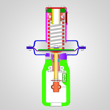
DIRECT (Model PDO) Actuator (see Fig:-A) extend the actuator stem with increasing are pressure and retract the stem with decreasing pressure.
REVERSE (Model PDC) Actuator (see Fig:-B) retract the actuator stem with increasing operating air pressure and extend the stem with decreasing pressure.
Remove the actuator from the valve in the following steps.
(a) Ensure plug face is not in contact with the seat – (apply aor pressure to reverse action
actuator).
(b) Remove the stem coupling.
(c) Unscrew the locking ring.
(d) Lift actuator off valve.
Remove the spring cover plate.
Release all spring compression by inserting ½ inch wide bar in the retainer slot and rotating in an
anti-clockwise direction.
Remove the diaphragm case screws and nuts and separate the diaphragm cases. (In the reverse action arrangement care must be taken to lift the top diaphragm case assembly perfectly straight with a slight rotary movement until the slide is clear of the stem).
Unlock travel stop nuts and indicator disc unscrew from stem. 6. Lift the diaphragm assembly and the actuator stem clear of the actuator, taking care to withdraw
the stem perfectly straight to avoid damaging the threads and ‘o’ rings in the reverse action
arrangement.
For PDC Actuator replace the ‘O’ ring, remove the yoke screw and seoarate the yoke from the diaphragm case or spring assembly.
For PDC Remove the old ‘O’ ring from the seal- box and replace eith new ones.
For PDC unscrew the stem lock nut and remove the diaphragm.
For PDO unscrew the collar nut and remove the diaphragm.
Slide the diaphragm button and the old diaphragm off the actuator stem.
Fit the new diaphragm on to the diaphragm, diaphragm collar, stem and stem lock nut assembly and secure the stem lock nut.
Fit the diaphragm, diaphragm collar, stem and stem lock nut assembly into the actuator without damaging the ‘O’ rings on a PDC actuator.
Bolt together the diaphragm casings ensuring the bolting is tightened evenly to ensure correct sealing and also prevent damage to casings.Unscrew the shaft of TMH (Part No. 23). At the stage bearing housing along with shaft will be decouple from the actuator stem.
Fit the travel indicator plate and travel plate locknuts onto the stem.
Using the spring adjuster the spring compression should be applied until the actuator
start to operate at the bench set figure detailed on the nameplate